Let's ignore the jumpers, these are for hardware hacking and troubleshooting.
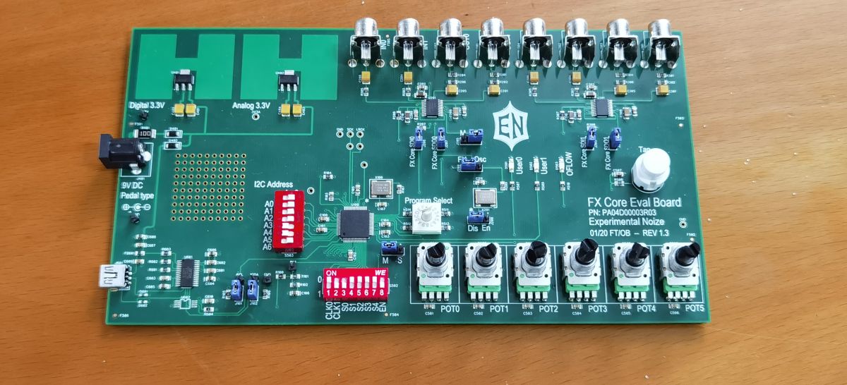
The main ones we care about are the S0-S4 at the bottom center of the board. These are pins that have their own pull-up resistors and are read by the FXCore every sample. You can read them by looking at the SWITCH SFR. Each switch has its own mnemonic code in the assembler so you don't need to know which bit is which. BTW the values are SW0-4, not S0-4 despite the label on the dev board. Here's how it works:
Code: Select all
cpy_cs		acc32, switch		; copy switch SFR into acc32
andi		acc32, sw0		; mask off all of the switches except s0
jz		acc32, switch_closed	; if the switch is set to ON, then do something
jmp		switch_open		; if not, jump to the switch_open routine

switch_closed:
; put some actions here to run if the switch is closed
jmp		done			; and jump to done when finished

switch_open:
; put some actions here to run if the switch is open
jmp		done			; and jump to done when finished

done:
xor		acc32, acc32		; must have an instruction after the last label, end of program
Code: Select all
; delay effect with bypass trails
; pot0 delay time
; pot1 delay feedback / repeat
; pot2 delay mix
; sw0 bypass

.mem	delay	30000

.rn	input	r0
.rn	feedback	r1
.rn	temp	r14
.rn	temp2	r15

; read input and put in register

cpy_cs	input, in0		; get input

; read bypass switch and mute input if we are in bypass
; this lets the trails ring out, we're just cutting the feed
; to the delay but leaving the output alone

cpy_cs	acc32, switch	; get switch
andi		acc32, sw0	; test for switch 0
jz		acc32, doBypass	; if the switch is closed, we bypass
jmp		doDelay		; if the switch is open, we do not bypass

doBypass:
xor		acc32, acc32	; clear acc
cpy_cc		input, acc32	; put zero in input

doDelay:
adds		feedback, input	; add feedback to input
wrdel		delay, acc32	; write result to delay line

wrdld		acc32, delay!		; put size of delay in acc32
cpy_cc		temp, acc32		; store in temp
cpy_cs		acc32, pot0_smth	; get pot0 value for delay time
multri		acc32, 0.95		; scale to 95%
addsi		acc32, 0.05		; now ranges from 5% to 100% (pretty close anyway)
multrr		temp, acc32		; scale knob value by size of delay

interp		acc32, delay		; get delay from current position, which is in the acc32

cpy_cc		temp, acc32		; put the delay audio in temp for a sec, so we can do feedback
cpy_cs		acc32, pot1_smth	; get pot1 for feedback
multrr		temp, acc32		; scale feedback to pot value
multri		acc32, 0.9		; limit feedback so it doesn't oscillate
cpy_cc		feedback, acc32		; store scaled feedback so we can add it in next sample

cpy_cs		acc32, pot2_smth	; get mix pot value
multrr		acc32, temp		; remember our delay audio is in temp!
adds		input, acc32		; add the delay out (scaled) to the input, gets us delay + dry mixed
cpy_sc		out0, acc32		; and send to output
So now we know about the main switches, which are designed to be accessed in our code any time. What about the other ones on the board?
On the same block as the SW0-SW4 user switches, we also have EN, which will bypass all audio processing on the FXCore by essentially connecting in0 to out0 and in1 to out1 internally. The chip is still running but you will only hear bypassed audio. This switch can be read in your program using the SWITCH SFR, same as SW0-SW4.
Code: Select all
cpy_cs		acc32, switch		; get switch input
andi		acc32, enabledb		; get enable pin value
Then at the other end of the block we have the PLL RANGE switches, which set the sample rate. These can be read using the BOOTSTAT register, which is only updated when the FXCore resets. This also means that the FXCore's sample rate can only change on a reset, so don't freak out if you flip the switches and you don't hear a change. Usually you will have a single sample rate in your program and you can design around whatever that is, but if for some reason you need to change the rate you can write some code to have your program adapt to that rate. PLL Range is the lowest two bits of BOOTSTAT.
IMPORTANT NOTE: BOOTSTAT is only read from the FXCore after a reset! If you change one of the pins that is part of this SFR, the FXCore won't update BOOTSTAT or change its own parameters until you reset it. So you can't change the I2C address or the PLL range on the fly, for example.
Code: Select all
; read PLL range
cpy_cs		acc32, BOOTSTAT		; get boot state
andi		acc32, 0x0003		; we just want the LSBs, 0 and 1

; pll range is in the acc.  00 = 12kHz, 01 = 24kHz, 10 = 32kHz, 11 = 48kHz
; your code can do whatever you'd like, such as changing filter coefficients or LFO range
I2C address is also read using the BOOTSTAT register
Code: Select all
cpy_cs		acc32, bootstat		; copy SFR BOOTSTAT into acc32
andi		acc32, 0xFFFF		; I2C address is in bits 3-9 of BOOTSTAT so mask off the lower half
sr		acc32, 3		; shift result right by 3 bits, now I2C address is in acc.  Ranges from 0-127 or 0x00-0x7F
How is this useful? Well, let's take the delay program example from above. If we want to allow the user to enable or disable the delay trails function normally we would have to dedicate one of our limited user switches to this purpose. But if you don't mind changing it when the power is off, you can use one of the I2C address pins to set it. This is ideal for something that doesn't get changed a lot, for example a DIP switch that you might put inside a pedal. Just remember that you've changed this address and you won't be able to program using the default 0x30 value unless you change it back!!! Also make sure that whatever you change the address to doesn't conflict with other devices in your pedal!
Code: Select all
; same delay effect, but uses I2C address pin 0 to enable or disable trails!
; this switches the I2C address between 0x30 and 0x31, make sure it doesn't conflict with other devices in your system!
; delay effect with bypass trails
; pot0 delay time
; pot1 delay feedback / repeat
; pot2 delay mix
; sw0 bypass
; I2CA0 trails enable

.mem	delay	30000

.rn	input	r0
.rn	feedback	r1
.rn	temp	r14
.rn	temp2	r15

; read input and put in register

cpy_cs	input, in0		; get input

; put high value in temp2 for later
wrdld		acc32, 0x7FFF	; fill upper bits
ori		acc32, 0xFFFF	; and lower bits
cpy_cc		temp2, acc32	; now store in temp2

; read bypass switch and mute input if we are in bypass
; this lets the trails ring out, we're just cutting the feed
; to the delay but leaving the output alone

cpy_cs		acc32, switch	; get switch
andi		acc32, sw0	; test for switch 0
jz		acc32, doBypass	; if the switch is closed, we bypass
jmp		doDelay		; if the switch is open, we do not bypass
xor		acc32, acc32	; if we are in trails bypass then we need to mute the delay output
cpy_cc		temp2, acc32	; so we put zero in temp2

doBypass:
xor		acc32, acc32	; clear acc
cpy_cc		input, acc32	; put zero in input
cpy_cs		acc32, BOOTSTAT		; get boot status SFR
andi		acc32, 0x0008		; I2CA0 is 3rd bit of BOOTSTAT
jz		acc32, doDelay		; if I2CA0 is low (default) then we do nothing here

doDelay:
adds		feedback, input	; add feedback to input
wrdel		delay, acc32	; write result to delay line

wrdld		acc32, delay!		; put size of delay in acc32
cpy_cc		temp, acc32		; store in temp
cpy_cs		acc32, pot0_smth	; get pot0 value for delay time
multri		acc32, 0.95		; scale to 95%
addsi		acc32, 0.05		; now ranges from 5% to 100% (pretty close anyway)
multrr		temp, acc32		; scale knob value by size of delay

interp		acc32, delay		; get delay from current position, which is in the acc32

multrr		acc32, temp2		; if we are in bypass AND trails is set to OFF, we mute here

cpy_cc		temp, acc32		; put the delay audio in temp for a sec, so we can do feedback
cpy_cs		acc32, pot1_smth	; get pot1 for feedback
multrr		temp, acc32		; scale feedback to pot value
multri		acc32, 0.9		; limit feedback so it doesn't oscillate
cpy_cc		feedback, acc32		; store scaled feedback so we can add it in next sample

cpy_cs		acc32, pot2_smth	; get mix pot value
multrr		acc32, temp		; remember our delay audio is in temp!
adds		input, acc32		; add the delay out (scaled) to the input, gets us delay + dry mixed
cpy_sc		out0, acc32		; and send to output